Help & User Guide
Everything you need to know about installing, configuring, and using Flow for Autodesk Inventor 2025–2027.
1. Introduction
Flow is an Autodesk Inventor add-in designed to make everyday property work faster, clearer, and more consistent. It replaces the repetitive cycle of opening iProperties dialogs, clicking through tabs, and manually finding fields with a single dockable panel that stays open while you design.
At its core is the Property Edit panel — a configurable, always-visible surface that shows only the properties your team uses, in the order you choose, with the input controls your process demands. Flow also includes live model inspection tools, an extendable module system, and comprehensive team-management features.
Quick facts:
Works in Inventor 2025, 2026, and 2027
Offline licence verification — no internet required for daily use
Shared team configuration via network folder or Vault
Full support for Inventor light and dark themes
One module: iLogic Rules
2. What Flow includes
Flow is organised as a core add-in plus three modules. The core provides the Property Edit panel and the Configuration dialog. Hover and Thickness are donor-licensed features. Modules add domain-specific capabilities.
Core features
| Feature | What it does |
|---|---|
| Property Edit panel | Edit configured properties on active documents or selected components |
| Hover Donor | Live interactive tooltip with property data and component highlighting in the graphics window |
| Thickness Donor | Live interactive model-thickness analysis with graphical feedback |
| Configuration dialog | Define properties, groups, categories, lists, appearance, and module behaviour |
| Property Copy / Paste | Transfer property values between components |
| Team configuration | Share layout and licence from a single network location |
Module overview
| Module | Purpose |
|---|---|
| iLogic Rules | Exposes external iLogic scripts as proper, labelled ribbon buttons |
3. Installation and first launch
Installing Flow
- Download the ZIP package for your Inventor version from the download page.
- Extract the ZIP to a temporary location.
- Run the install script for your version:
Install_Flow_20xx.cmd. Administrator rights are not required. - Start Autodesk Inventor. The Flow ribbon tab will appear automatically.
What is installed
Flow.dll— the main add-in assemblyFlow.Inventor.addin— the Inventor add-in descriptorlibsodium.dllandNSec.Cryptography.dll— licence verification librariesModules\— optional module DLLs (one subfolder per module)Resources\— icons, images, and assetsConfig\— default configuration (created on first run)
Each Inventor version (2025, 2026, 2027) requires its own install package.
First launch
On first launch, Flow creates a default configuration and the Property Edit panel opens with a useful starting set of properties. The configuration can be refined later through the Configuration dialog.
4. Licence and theme support
Flow uses Ed25519-signed local .lic files for licence verification. Day-to-day use does not require an internet connection.
Base functionality (free)
- Property Edit panel (light theme)
- Team configuration
Licensed features
A small donation unlocks the features below. Learn more and donate.
- Hover — live interactive property inspection in the graphics window
- Thickness — live interactive model-thickness analysis with graphical feedback
- Full dark-mode support — all Flow UI adapts to Inventor's dark theme
- iLogic Rules module — distribute iLogic scripts as ribbon buttons
How licensing works
- After donating, you receive a
.licfile by email. - Place the
.licfile in the same folder as yourFlow_config.xmlconfiguration file. - Flow reads the licence automatically at startup. No activation steps required.
Team deployment
Place the .lic file in the shared configuration folder and every team member is automatically licensed when Flow loads the shared config. No per-user setup.
5. The Flow workspace in Inventor
After installation, Flow integrates into two main areas of Inventor:
- The Flow ribbon tab — providing access to Property Edit, Hover, Thickness, Configuration, About, Copy, Paste, and module-specific commands.
- The Property Edit panel — a dockable window that stays visible while you work.
6. Property Edit panel — the heart of Flow
6.1 What the panel does
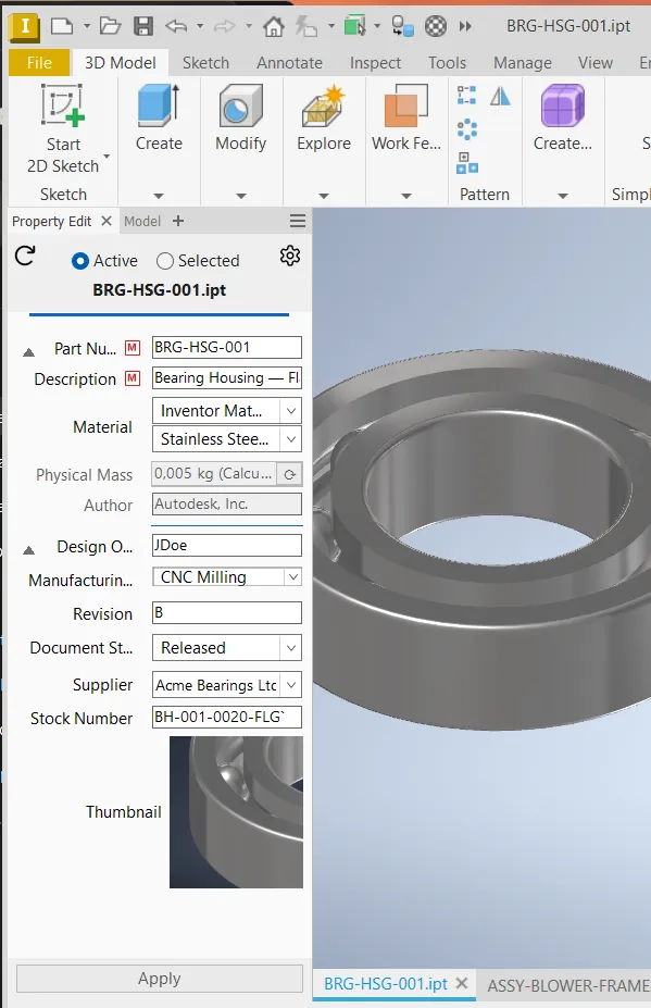
The Property Edit panel replaces Inventor's generic iProperties dialog with a focused, configurable surface. Instead of showing every possible property, the panel shows only the properties you have configured for the current document's category.
You can use the panel to edit:
- The active part, assembly, or drawing (Active Document scope)
- A selected component occurrence inside an assembly (Selected Component scope)
The panel refreshes automatically when you change selection, so it always shows the current context.
6.2 Editing a property
- Open the Property Edit panel (or ensure it is docked).
- Select the document context: Active Document or Selected Component.
- For the Selected Component scope, click the component you want to edit in the graphics area.
- Edit one or more fields.
- Press Enter or click Apply to commit the changes.
Flow is careful about document changes — it only writes a property when the value actually changes. This means you can inspect a document in the panel without dirtying it.
6.3 Read-only properties
Some properties are valuable to display but should not be edited by users. Marking a property definition as Read-Only in the configuration achieves this.
Common use cases: reference values, master identifiers controlled by a separate process, or read-only versions of properties shown alongside editable copies. Read-only fields appear with a distinct visual style in the panel.
6.4 Mandatory properties
Marking a property as Mandatory requires it to have a non-empty value before the Apply button succeeds. This is ideal for critical metadata that must always be present, such as Part Number, Description, or Material.
How mandatory fields behave:
- An M badge appears next to the property label for all mandatory fields.
- On the first Apply attempt with empty mandatory fields, the empty rows gain a yellow background and bold red text. No dialog appears yet.
- On a second Apply attempt while highlights are still showing, a dialog box lists the empty mandatory fields.
- As soon as the user enters a value, the highlight clears automatically.
- Mandatory overrides Allow blank on lists — a blank value will not be accepted even if the list permits it.
Note: YesNo (checkbox) properties are skipped from the mandatory check since a checkbox always has a value. The M badge is still shown.
6.5 Lists and controlled input
Connect a property to a configured list and users select from approved values instead of typing free-form text. This is one of Flow's strongest data-quality features.
A list can behave in two ways:
- Suggested list: users see the list as a dropdown but can type their own value
- List only: users must pick one of the configured values — free-form input is blocked
Allow blank: When List only is enabled, checking Allow blank adds an empty entry to the top of the dropdown so users can explicitly select "no value." When disabled, an empty value on a List only field triggers a not-in-list warning with a yellow highlight and exclamation indicator. Note that if the property is also marked as Mandatory, Allow blank has no effect — the field cannot be left empty.
Categorised lists: Lists can include category items that organise values into a tree structure. Categories appear as bold, non-selectable headers in the dropdown, with their leaf values nested underneath.
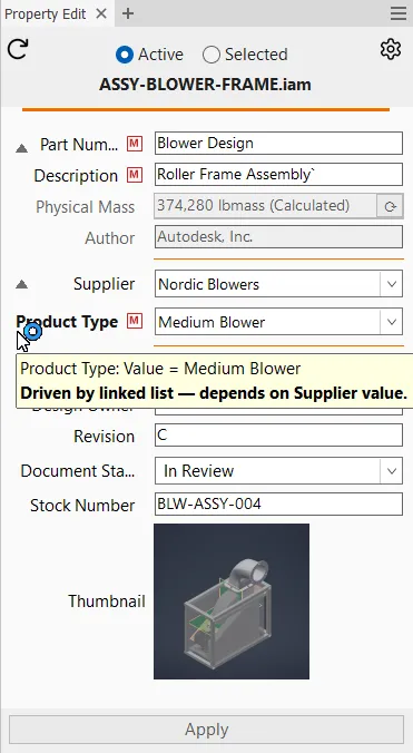
6.6 Linked lists — one choice drives another
Linked lists allow the available values for one property to depend on the current value of another property. Flow calls the first property the source and the second the dependent.
When the source property changes, the dependent property's list updates immediately. If the dependent is list only, it snaps to the first valid value automatically, keeping the cascade consistent.
6.7 Property groups — organising your panel
Properties are organised into groups — collapsible sections inside the panel. Groups make the panel scannable and allow you to separate frequently used fields from reference data.
A common structure:
- Group 1: General — Part Number, Description, Material, Mass
- Group 2: Production — Finish, Supplier, Stock Number
- Group 3: Reference — Revision, Author, Document Status (collapsed by default)
6.8 Document categories — layout by document type
Flow uses document categories to determine which property groups appear for each document. Categories work through matching rules that evaluate the active document.
Rule types:
- File extension — e.g. match
.iptfor parts,.iamfor assemblies - Special type — e.g. Sheet Metal, Weldment Assembly, Content Center part
- iProperty value — e.g. match when custom property "SubassyType" equals "Electrical"
6.9 Category accents and thumbnails
The panel can show a coloured accent bar at the top and an optional thumbnail of the current document. The accent colour instantly confirms which document category you are viewing (e.g. blue = Part, orange = Assembly, purple = Drawing). The thumbnail provides visual confirmation that you are editing the right component.
6.10 Expressions and the Fx indicator
When a property is controlled by an expression (a formula), Flow shows an Fx indicator on the property label. Hovering the indicator shows the expression text. Right-clicking a property row lets you edit the formula directly.
6.11 Special properties (BOM, Material, Mass)
| Property | Behaviour |
|---|---|
| Physical Mass | Read-only display of the calculated mass. An update button forces Inventor to recalculate. |
| BOM Structure | Dropdown selector for the component's BOM structure (Normal, Phantom, Reference, etc.). |
| Material | Two-part dropdown: first pick a material library, then pick a material from that library. |
6.12 Type validation — number properties
Properties configured as Number type enforce numeric input. When a stored value is not a valid number, the panel shows a yellow background, red bold text, and an exclamation indicator on the label.
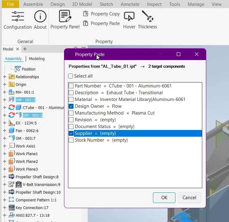
6.13 Copy and paste properties
The Flow ribbon includes Copy Properties and Paste Properties buttons. This lets you transfer a block of configured property values from one component to another. Only properties that are both configured in Flow AND present on the target document are transferred.
6.14 Scope — Active Document vs Selected Component
| Mode | What you are editing |
|---|---|
| Active Document | The currently active part, assembly, or drawing |
| Selected Component | A single component occurrence you select in the assembly graphics area |
Selected Component mode lets you edit an occurrence's properties without opening the file separately.
6.15 Model State support
Flow supports Inventor Model States. When a document has multiple model states, the panel shows the properties for the active model state.
6.16 Multi-edit — editing multiple components at once
Multi-edit lets you select several components in an assembly with Ctrl+click or Shift+click and edit their shared properties in a single operation.
How it works:
- Set the panel scope to Selected Component.
- Ctrl+click two or more components in the graphics window or assembly browser.
- The panel shows properties that are common across all selected components. Any component-specific values appear as a greyed-out "(varies)" indicator.
- Edit one or more properties and press Apply. The new values are written to every selected component simultaneously.
Multi-edit is ideal for batch operations like setting Material, Author, or custom iProperties across entire subassemblies in a single step.
7. Hover — live interactive property inspection
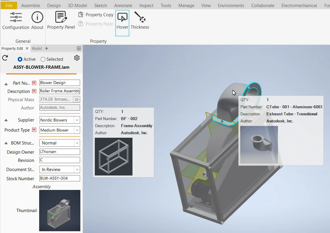
Hover is a real-time inspection tool for assemblies. Activate it from the ribbon, move your mouse over any component, and a tooltip appears with your selected property data.
What Hover shows
- Configured property values for the hovered component
- All instances of the component highlighted in the assembly
- Optional thumbnail of the component
- Quantity information
- Mass display (when configured)
Configuration
In the Configuration dialog under Hover, you can set: property group to display, thumbnail visibility, and tooltip opacity (0–100%).
8. Thickness — live interactive model-thickness analysis
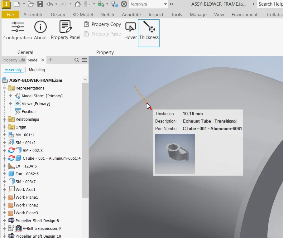
Thickness is a live inspection tool that evaluates wall thickness at the cursor position on a part surface. It is particularly useful for sheet metal review, thin-walled plastic part inspection, and quick design verification.
Click the Thickness button on the ribbon, move the cursor across surfaces, and see the wall thickness at each point in real time. Configuration options include property group display, thumbnail, opacity, visibility of the measurement ray, and ray length.
9. Configuration — shaping Flow to your workflow
The Configuration dialog is where a CAD administrator or power user defines how Flow behaves. Access from the Flow ribbon: Configuration.
9.1 General settings
- Property panel title
- Ribbon tab name
- Logging enable/disable
- Module enablement
- Configuration storage location
9.2 Properties — defining what to show
Each property definition includes: Name, Display Name, Custom Property toggle, Read-Only toggle, Mandatory toggle, Type (Text/Number/YesNo), Tooltip, Sort Order, optional list assignment, optional linked-list configuration, and optional hide rules.
9.3 Lists — standardising text input
Define named collections of values with a toggle for List only enforcement and Allow blank to add an empty entry. Lists can include category items that organise values into a navigable tree structure.
9.4 Groups — organising the panel
Groups define collapsible sections with a name, initial collapse state, and an ordered list of property IDs.
9.5 Categories — matching documents to layouts
Categories route documents to layouts using rule-based matching (file extension, special type, iProperty value). All rules within a category must pass (AND logic). Categories are evaluated top to bottom — place more specific categories first.
9.6 Colours and appearance
Each category supports an accent colour, light accent, and dark accent. Flow automatically selects the appropriate shade based on the active Inventor theme.
9.7 Modules — managing add-on capabilities
Installed modules appear in the navigation pane. Each can be enabled/disabled globally and shows licence status.
10. Module 1: iLogic Rules Donor
The iLogic Rules module turns external iLogic scripts into proper, labelled ribbon buttons. Define the rule file path, pick an icon, write a tooltip, and choose which document types the button appears for.
11. Team distribution and shared configuration
Flow is designed for team deployment. Place configuration files in a shared network folder or Vault workspace. Every Flow installation points to that folder. Changes propagate to all users at next restart.
Files involved: Flow_config.xml, Flow_Global.xml, .lic file, and module configs.
How shared config paths work:
- A CAD administrator opens the Configuration dialog on their machine and sets the configuration path to a shared network folder or Vault location.
- Flow writes this path to
%appdata%\Autodesk\Inventor 202X\Addins\Flow\Flow_Global.xml. - The administrator distributes this single
Flow_Global.xmlfile to all users' corresponding AppData directories. - Each user restarts Inventor and Flow automatically uses the shared config — no per-user setup required.
This approach means the admin configures once, tests locally, and only needs to distribute one small pointer file. All actual configuration lives in the shared location.
Recommended rollout:
- Define properties, lists, groups, and categories in a pilot environment.
- Validate with a few power users.
- Place the approved configuration in a shared, read-only location.
- Distribute the
.licfile to the same folder. - Distribute
Flow_Global.xmlto all users via script, group policy, or SCCM. - Communicate conventions to the team.
12. Diagnostics and logging
Flow supports diagnostic logging for troubleshooting. Logging is enabled from Configuration > General and defaults to off. Diagnostics are written to %TEMP%\Prop-tools\.
13. Update notifications
Flow can notify users when a newer build is available. The notification is informational only — Flow never updates itself automatically.
14. Practical setup examples
Example A: Simple part and assembly metadata
Goal: Clean property panel with essential fields only.
Setup: Define properties (Part Number, Description, Author, Material). Create one "General" group. Create "Part" (.ipt) and "Assembly" (.iam) categories both assigning "General". Add a Material list set to List Only.
Example B: Sheet metal workflow
Goal: Show extra fields only for sheet metal parts.
Setup: Add Thickness, Finish, K-Factor properties. Create "Sheet Metal" group. Create "Sheet Metal" category with rules: .ipt AND Special type "Sheet metal". Assign "General" + "Sheet Metal" groups. Give it a distinct accent colour and ensure it sorts before the generic "Part" category.
Example C: Team iLogic distribution
Setup: Store .iLogicVb files in a shared network folder. Add rule entries with clear labels, tooltips, and document type filters. Check "Show in ribbon" for one-touch access.
15. Frequently asked questions
Does Flow require internet access during normal use?
No. Licence verification is offline. Update notifications check on a best-effort basis and fail silently.
Can I run Flow with a shared team configuration?
Yes. Point all installations to a shared network folder or Vault workspace containing the config files.
Can different document types show different panel layouts?
Yes. The document category system is built for this. Each category can have its own set of property groups.
Can I force users to pick only from approved values?
Yes. Use lists with the List only option. Enable Allow blank if you want users to be able to explicitly choose "no value" from the dropdown.
Can I require certain properties to always have a value?
Yes. Mark properties as Mandatory in the configuration. Flow will highlight empty mandatory fields and block Apply until they are filled.
Can I display read-only reference properties?
Yes. Mark properties as Read-Only in the configuration.
Can I hide properties conditionally?
Yes. Use hide rules on property definitions.
Can I expose company iLogic rules as normal buttons?
Yes. The iLogic Rules module is built for this.
Where are diagnostics written?
%TEMP%\Prop-tools\ — only when logging is enabled.
Does Flow work with Model States?
Yes. The panel shows properties for the active model state.
Which Inventor versions does Flow support?
Inventor 2025, 2026, and 2027. Each version requires its own install package.
Can I use Flow in both light and dark Inventor themes?
Yes, with a licence. Free users have the light theme. Licensed users also get full dark-mode support.